Crushing – Traces from the manuscript..!
Eli Whitney Blake invented the first successful mechanical rock breaker, the Blake jaw crusher patented in 1858. History tells us, it was in 1830, the first US patent was issued on a rock crushing machine. It covered a device which,
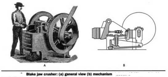
Eli Whitney Blake invented the first successful mechanical rock breaker, the Blake jaw crusher patented in 1858.
History tells us, it was in 1830, the first US patent was issued on a rock crushing machine. It covered a device which, in a crude way, incorporated the drop hammer principle later used in the famous stamp mill, whose history is so intimately linked with that of the golden age of mining. In 1840, another patent was issued, which comprised a wooden box containing a cylindrical drum apparently of wood also on which a number of iron knobs, or hammers, were fastened; the expectation was that this drum, when revolved at about 350 RPM, would shatter the rock fed into the top of the box. This device, although it was conceived as an impact crusher and thus would rate as a forerunner of the hammermill, bore a somewhat closer resemblance to the single sledging-roll crusher. There is no evidence that either of these early inventors carried their work through to fruition.
Eli Whitney Blake invented the first successful mechanical rock breaker, the Blake jaw crusher patented in 1858. Blake adopted a mechanical principle familiar to all students of mechanics, the powerful toggle linkage. That his idea was good is attested to by the fact that the Blake type jaw crusher is today the standard by which all jaw crushers are judged, and the leading machine of the class for heavy duty primary crushing service.
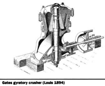
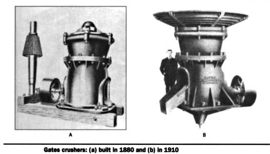
The gyratory principle was the basis of several rudimentary designs, patented between 1860 and 1878, none of which embodied practical mechanical details at least, not in the light of our present-day knowledge of the art. Then, in 1881, Philetus W. Gates was granted a patent on a machine which included in its design all of the essential features of the modern gyratory crusher. The first sale on record antedates the patent by several months, a No. 2 crusher, sold to the Buffalo Cement Co. in 1880. That was the first of several thousand gyratory crushers which carried the name of Gates to the far corners of the earth.
An interesting sidelight of these early days occurred in 1883 when a contest was staged between a Blake jaw crusher and a Gates gyratory crusher. Each machine was required to crush 9 cubic yard of stone, the feed-size and discharge settings being similar. The Gates crusher finished its quota in 21 minutes, the Blake crusher in 65 minutes, which must have been a sad disappointment to the proponent of the Blake machine, who happened to be the challenger.
Manual Mining
For some years after these pioneer machines were developed, requirements, viewed in the light of present practice, were very simple. Mining and quarrying, whether underground or open-pit, was done by hand; tonnages generally were small, and product specifications simple and liberal.
In the milling of precious metal ores, stamp mills were popular as the final reduction machine. These were generally fed with an ore size that could be produced handily by one break through the small gyratory and jaw crushers which served as primary breakers. Even in large underground mining operations there was no demand for large crushers; increased tonnage requirements were met by duplicating the small units. For example, in 1915, at the huge Homestake operation, there were no less than 20 Gates’ small gyratory crushers sizes No. 5 & 6 to prepare the ore for the batteries of >2500 stamp mills.
Most commercial crushed stone plants were small, and demand for small product sizes practically non-existent. Many plants limited output to two or three products. Generally the top size was about 2.5 to 3” ring-size; an intermediate size of about 1.5” or thereabouts, might be made, and the dust, or screenings, removed through openings of about 0.25”. In ballast plants the job was even more simple, one split and an oversize re-crush being all that was needed.
Many small process plants consisted of one crusher, either jaw or gyratory rock crushers, one elevator and one screen. Recrushing, if done, was taken care of by the same machine handling the primary break. The single crusher, when of the gyratory type, might be any size from the No. 2 (6” opening) to the No. 6 with 12-in. opening.
When demand grew beyond the capabilities of one crusher, it was generally a simple matter to add a second machine to take care of the recrushing or secondary crushing work. A popular combination, for example, consisted of a No. 6 primary and a No. 4 secondary, or possibly a 20- x 10-in., or 24- x 12-in. primary jaw, followed by one of the small gyratories. When the business outgrew the capacity of this sort of plant, it was not unusual to double up, either in the same building, or by erecting an entirely separate plant adjacent to the original one.
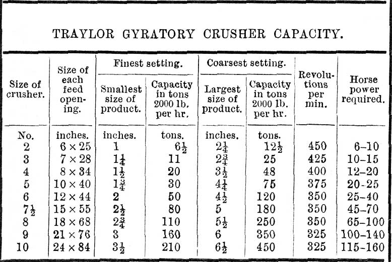
Crusher manufacturers were not standing still during these early years. In the gyratory line, for example, the No. 2 was the first popular size, and larger machines were developed from time to time up to the No. 6, then the No. 7.5.
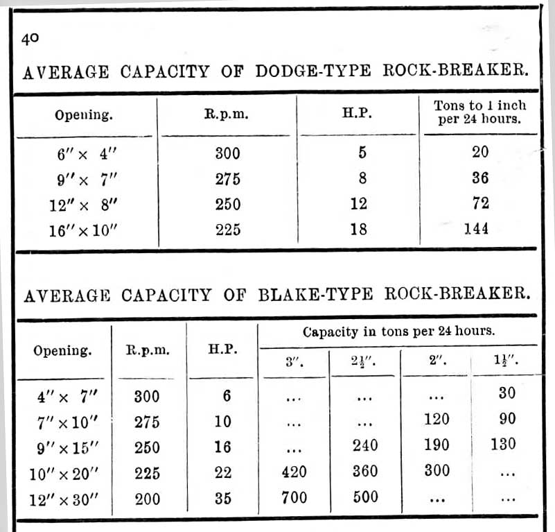
Blake Jaw Crusher
The steam shovel began to change the entire picture of open-pit working. With the steam shovel came the really ‘‘huge” No. 8 crusher, with its 18” receiving opening. Up to this time the jaw crusher had kept pace with the gyratory, both from the standpoint of receiving opening and capacity, but now the gyratory stepped into the leading position, which it held for some 15 years. Once the ice was broken, larger and larger sizes of the gyratory type of crusher were developed rapidly, relegating the once huge No. 8 machine to the status of a secondary crusher. This turn toward really large primary crushers started just a few years before the turn of the century, and in 1910 crushers with 48” receiving openings were being built.
Along about this time the jaw crusher suddenly came back to life and stepped out in front with a great contribution to the line of mammoth-size primary crushers: the 84” x 60” machine built by the now Joy Mining Machinery for a trap rock quarry in eastern Pennsylvania. This big crusher was followed by a No. 10 (24” opening) gyratory crusher for the secondary break. Interest created by this installation reawakened the industry to the possibilities of the jaw crusher as a primary breaker, and lines were brought up-to-date to parallel the already developed gyratory lines.
Although his machines never came into general use in the industry, Thomas A. Edison ranks as a pioneer in the development of the large primary breaker and credited with the announcement of a very interesting and constructive bit of reasoning, which was the basis of his development. Concerned at the time with the development of a deposit of lean magnetic iron ore where he was using a number of the small jaw crushers then available for his initial reduction. Realizing that to concentrate this ore at a cost to permit marketing it competitively meant cutting every possible corner, he studied the problem of mining and crushing the ore as one of the steps susceptible of improvement.
In approaching the problem, Edison reasoned that the recoverable energy in a pound of coal was approximately equal to the available energy in one pound of 50% dynamite; but the cost per pound of the dynamite was about 100 times that of the coal. Furthermore, a large part of the dynamite used in his mining operation was consumed in secondary breaking to reduce the ore to sizes that the small primary crushers would handle. The obvious conclusion was that it would be much cheaper to break the large pieces of ore by mechanical rather than by explosive energy.
With that thesis as a starting point, he set out to develop a large primary breaker, a development which culminated several years later in the huge and spectacular 8” x 7” Edison rolls. A description of the action of this machine will be found in a later section of this series. During the early years of the present century these giant machines created considerable interest, and several were installed in this country. However, they never became popular, and interest swung back to the more versatile gyratory and jaw types. Edison rolls were also developed in smaller sizes for use as secondary and reduction crushers.
Mechanical Screening…
Mechanical screening, often just called screening, is the practice of taking granulated ore material and separating it into multiple grades by particle size. This practice occurs in a variety of industries such as mining and mineral processing, agriculture, pharmaceutical, food, plastics, and recycling. A method of separating solid particles according to size alone is called screening.
General categories
Screening falls under two general categories: dry screening, and wet screening. From these categories, screening separates a flow of material into grades, these grades are then either further processed to an intermediary product or a finished product. Additionally, the machines can be categorized into a moving screen and static screen machines, as well as by whether the screens are horizontal or inclined.
Applications
The mining and mineral processing industry uses screening for a variety of processing applications. For example, after mining the minerals, the material is transported to a primary crusher. Before crushing large boulder are scalped on a shaker with 0.25 in (6.4 mm) thick shielding screening. Further down stream after crushing the material can pass through screens with openings or slots that continue to become smaller. Finally, screening is used to make a final separation to produce saleable products based on a grade or a size range.
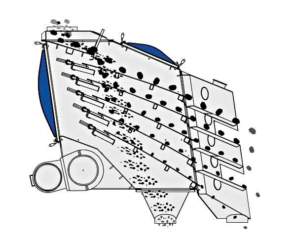
Process
A screening machine consist of a drive that induces vibration, a screen media that causes particle separation, and a deck which holds the screen media and the drive and is the mode of transport for the vibration.
There are physical factors that makes screening practical. For example, vibration, g force, bed density, and material shape all facilitate the rate or cut. Electrostatic forces can also hinder screening efficiency in way of water attraction causing sticking or plugging, or very dry material generate a charge that causes it to attract to the screen itself.
As with any industrial process there is a group of terms that identify and define what screening is. Terms like blinding, contamination, frequency, amplitude, and others describe the basic characteristics of screening, and those characteristics in turn shape the overall method of dry or wet screening.
In addition, the way a deck is vibrated differentiates screens. Different types of motion have their advantages and disadvantages. In addition media types also have their different properties that lead to advantages and disadvantages.
Finally, there are issues and problems associated with screening. Screen tearing, contamination, blinding, and dampening all affect screening efficiency.
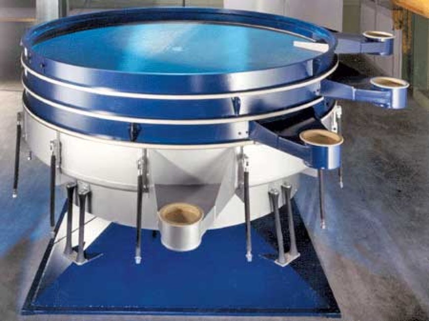
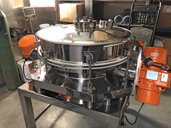
Tumbler screening technique
An improvement on vibration, vibratory, and linear screeners, a tumbler screener uses elliptical action which aids in screening of even very fine material. As like panning for gold, the fine particles tend to stay towards the center and the larger go to the outside. It allows for segregation and unloads the screen surface so that it can effectively do its job. With the addition of multiple decks and ball cleaning decks, even difficult products can be screened at high capacity to very fine separations.
Tensioned screen media
Tensioned screen cloth is typically 4 feet by the width or the length of the screening machine depending on whether the deck is side or end tensioned. Screen cloth for tensioned decks can be made with hooks and are attached with clamp rails bolted on both sides of the screen box. When the clamp rail bolts are tightened, the cloth is tensioned or even stretched in the case of some types of self-cleaning screen media. To ensure that
the center of the cloth does not tap repeatedly on the deck due to the vibrating shaker and that the cloth stays tensioned, support bars are positioned at different heights on the deck to create a crown curve from hook to hook on the cloth. Tensioned screen cloth is available in various materials: stainless steel, high carbon steel and oil tempered steel wires, as well as moulded rubber or polyurethane and hybrid screens (a self-cleaning screen cloth made of rubber or polyurethane and metal wires).
Commonly, vibratory-type screening equipment employs rigid, circular sieve frames to which woven wire mesh is attached. Conventional methods of producing tensioned meshed screens has given way in recent years to bonding, whereby the mesh is no longer tensioned and trapped between a sieve frame body and clamping ring; instead, developments in modern adhesive technologies has allowed the industry to adopt high strength structural adhesives to bond tensioned mesh directly to frames.
Modular screen media
Modular screen media is typically 1 foot large by 1 or 2 feet long (4 feet long for ISEPREN WS 85) steel reinforced polyurethane or rubber panels. They are installed on a flat deck (no crown) that normally has a larger surface than a tensioned deck. This larger surface design compensates for the fact that rubber and polyurethane modular screen media offers less open area than wire cloth. Over the years, numerous ways have been developed to attach modular panels to the screen deck stringers (girders). Some of these attachment systems have been or are currently patented. Self-cleaning screen media is also available on this modular system.
Perforated & Punch Plate
On a crushing and screening plant, punch plates or perforated plates are mostly used on scalper vibrating screens, after raw products pass on grizzly bars. Most likely installed on a tensioned deck, punch plates offer excellent wear life for high-impact and high material flow applications.
Synthetic screen media (typically rubber or polyurethane)
Synthetic screen media is used where wear life is an issue. Large producers such as mines or huge quarries use them to reduce the frequency of having to stop the plant for screen deck maintenance. Rubber is also used as a very resistant high-impact screen media material used on the top deck of a scalper screen. To compete with rubber screen media fabrication, polyurethane manufacturers developed screen media with lower Shore Hardness. To compete with self-cleaning screen media that is still primarily available in tensioned cloth, synthetic screen media manufacturers also developed membrane screen panels, slotted opening panels and diamond opening panels. Due to the 7-degree demoulding angle, polyurethane screen media users can experience granulometry changes of product during the wear life of the panel.
www.911metallurgist.com
Hits: 46